Router on a Stick VLAN Configuration with SwOS on the Mikrotik CRS328-24P-4S+RM Switch
My homelab grew quite a bit over the past years. And with that, my networking needs also changed: stricter firewall rules, segregating untrusted IoT devices into separate networks, traffic prioritization, and more. I wanted to document my switch and VLAN configuration. And maybe this is useful for someone else, too.
Mikrotik CRS328-24P-4S+RM
The Mikrotik CRS328-24P-4S+RM is a beefy Layer 3 (L3) switch. It features 24 Gigabit Power over Ethernet (PoE) ports and four 10 Gbps SFP+ ports. It has a 500W power supply, so it’ll be able to serve as a core switch for my homelab for a long time. It’s rack-mountable and was significantly cheaper than comparable Ubiquiti gear I was considering at the time of the purchase. I also replaced its stock fans with Noctua NF-A4x20s, making it completely silent. As long as I don’t use too many PoE devices and keep an eye on the temperatures, these fans will dissipate enough heat for the time being. For routing, I use OPNsense, so I only need the L2 capabilities of the Mikrotik switch, which is why I run it on SwOS instead of RouterOS. So, instructions in this guide also refer to SwOS.
Terminology
In computing, a router on a stick, also known as a one-armed router, is a router that has a single physical or logical connection to a network. It is a method of inter-VLAN (virtual local area networks) routing where one router is connected to a switch via a single cable.
When configuring VLANs, we usually encounter three types of port configurations (Cisco lingo):
- Access Port
Port carrying untagged traffic for one VLAN - Trunk Port
Port carrying tagged traffic for multiple VLANs - Hybrid Port
Port carrying tagged and untagged traffic for multiple VLANs
The traffic of the native VLAN may traverse a trunk port.
VLAN Overview
I like the convention of matching the third octet of the IP with the VLAN ID. I.e., assigning the VLAN with the ID 10 the address 192.168.10.0/24. Here is an overview of the VLANs I use:
| Description | VLAN ID | Subnet |
|---|---|---|
| Native | 1 | 192.168.1.0/24 |
| Management | 10 | 192.168.10.0/24 |
| VPN | 20 | 192.168.20.0/24 |
| Clear | 30 | 192.168.30.0/24 |
| Guest | 40 | 192.168.40.0/24 |
Port Mapping
Here is how we’re going to use the ports of the switch:
| Port | Description | VLANs |
|---|---|---|
| 1 | Trunk port connecting OPNsense | 1 (untagged), 10, 20, 30, 40 |
| 2-3 | Not used | |
| 4 | Hybrid port to Ubiquiti Unifi AP | 10 (untagged), 20, 30, 40 |
| 5-8 | Access ports connecting Management VLAN | 10 |
| 9-12 | Access ports connecting VPN VLAN | 20 |
| 13-16 | Access ports connecting Clear VLAN | 30 |
| 17-20 | Access ports connecting Guest VLAN | 40 |
| 21-24 | Access ports connecting native VLAN | 1 (untagged) |
| SFP1-SFP4 | Not used |
Note the following:
- The trunk port carries all tagged VLAN traffic from the switch to OPNsense
- The hybrid port carries the tagged traffic of VLANs 20, 30, and 40 made available by the UniFi access point (AP) via WiFi. We also allow untagged VLAN 10 traffic because UniFi devices must communicate over an untagged network to be adopted by a UniFi controller. We could use VLAN 1 for this, but I like to use VLAN 1 for debugging and instead adopt UniFi devices over the management network.
- For security reasons, connecting to the management network is only allowed via physical cable connection
- The guest network is only available via WiFi
Configure SwOS
The only thing missing now is configuring the VLANs. First, we enable Independent VLAN Lookup (IVL) on the System tab. We then add our VLANs and configure port isolation on the VLANs tab:

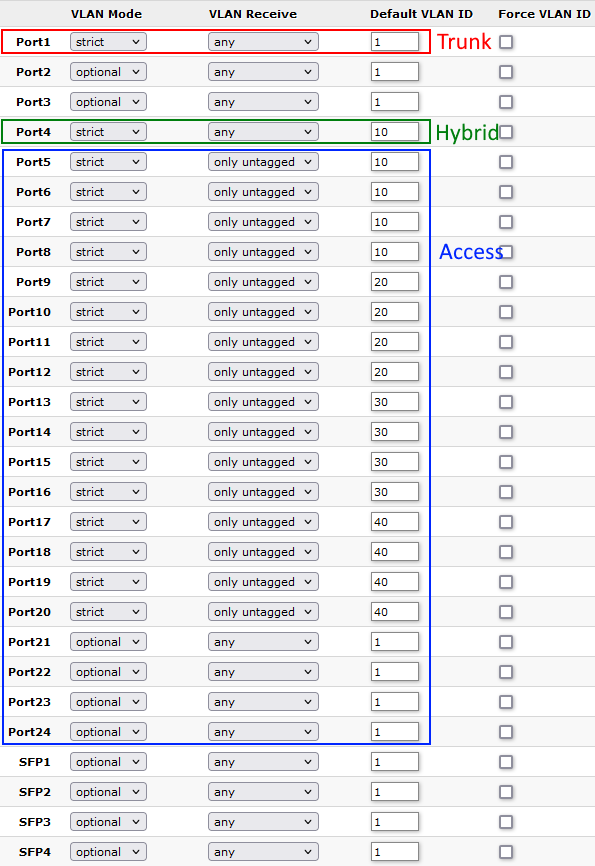
On the VLAN tab, we configure trunk, hybrid, and access ports:

Easy as that! Check the official Mikrotik docs for more VLAN example configurations.
